Blade vibration in turbomachinery components may lead to unwanted acoustic noise and material fatigue. The vibration is often caused by unsteady aerodynamic pressure forces on the surface of the blades. These pressure forces can be related to a wide variety of different physical mechanisms. Hence, predicting blade vibration at the design stage of a compressor or turbine is challenging. As a result, turbomachinery components are often tested over their anticipated operating range in order to investigate potential blade vibration issues.
The proper interpretation of vibration test data is important for providing feedback in the design cycle. However, our understanding of forcing mechanisms and their relationship to vibration characteristics is often limited. The literature often uses ambiguous vocabulary without a specific mathematical representation to describe these characteristics.
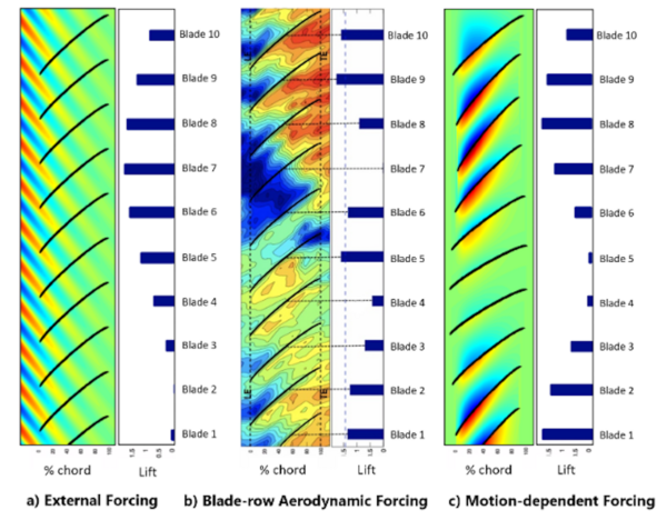
Investigators at the Notre Dame Turbomachinery Laboratory (NDTL) have recently developed a unique description of the different forcing mechanisms relevant to blade vibration in compressors. The physical mechanisms were grouped into three main categories, as shown in Figure 1: a) external forcing, b) blade-row aerodynamic forcing, and c) motion-dependent forcing. Next, mathematical models were proposed for each category. Simulation results were obtained for each model and the results were compared to experimental data, as shown in Figure 2. A key result is that each category’s distinct mathematical form results in distinct temporal characteristics of the vibration response. Therefore, this framework enables the use of temporal characteristics of measured blade vibration to identify the aerodynamic forcing mechanism(s) causing the vibration.
Additional information can be found in the forthcoming IGTI conference paper: “Aerodynamic Forcing Models for Compressor Aeromechanics”, in Turbo Expo: Power for Land, Sea, and Air, American Society of Mechanical Engineers, expected Summer 2022 (GT2022-80481). Please send inquiries to ndturbo@nd.edu.

Figure 1: Schematic representation of the unsteady pressure field for three categories of aerodynamic forcing. Bar graph right of contours represents the net integrated blade force, or lift, for each pressure field.

Figure 2: Temporal response for each category of forcing functions. Top: Simulations using the forcing function models proposed in this paper. Bottom: Experimental data from a) NDTL b) Kane [1] c) Holzinger et al. [2].
[1] Kane, M., 2017. “Aeromechanical response of an axial compressor in stall”. Master’s thesis, University of Notre Dame, Notre Dame, Indiana.
[2] Holzinger, F., Wartzek, F., Jϋngst, M., Schiffer, H.-P., and Leichtfuss, S., 2016. “Self-excited blade vibration experimentally investigated in transonic compressors: Rotating instabilities and flutter”. Journal of Turbomachinery, 138(4).
By Valerie Hernley, Aleksandar Jemcov, Scott C. Morris
Published by Jasmin Avila-Sacco
Originally published by at turbo.nd.edu on May 18, 2022.